
LM3914 Dot/Bar Display Driver
Datasheet: PDF
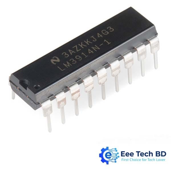
The DIP (through-hole, dual-inline package) version of this chip has 18 pins, and both a dot and notch to indicate polarity.
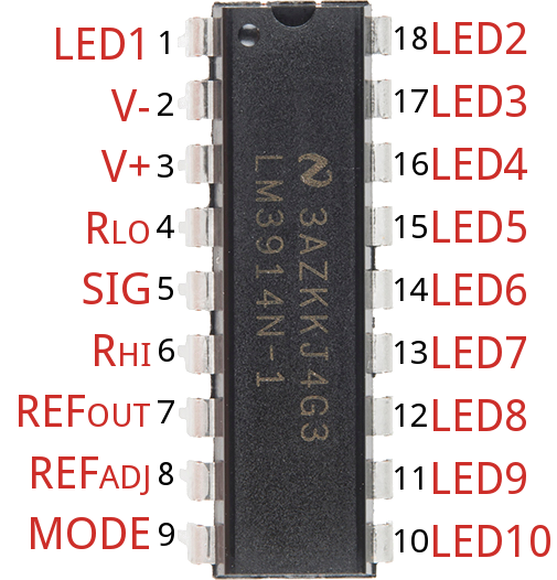
Over half of the pins are in charge of driving the LEDs. The remaining pins are used for power, reference voltages, and control of the IC. Here is an overview of the chip’s pinout:
| Pin # | Pin Name | Pin Function | Pin # | Pin Name | Pin Function | |
|---|---|---|---|---|---|---|
| 1 | LED 1 | First (lowest value) LED | 18 | LED 2 | 2nd LED | |
| 2 | V− | Ground | 17 | LED 3 | 3rd LED | |
| 3 | V+ | Supply voltage (3-25V) | 16 | LED 4 | 4th LED | |
| 4 | RLO | Divider low voltage | 15 | LED 5 | 5th LED | |
| 5 | Signal In | Analog signal in | 14 | LED 6 | 6th LED | |
| 6 | RHI | Divider high voltage | 13 | LED 7 | 7th LED | |
| 7 | Ref Out | Reference output voltage | 12 | LED 8 | 8th LED | |
| 8 | Ref Adj | Voltage reference adjust | 11 | LED 9 | 9th LED | |
| 9 | Mode | Dot/Bar mode select | 10 | LED 10 | Last (higest analog input) LED |
That may seem a daunting list of pins and reference voltages to supply, but in reality it can be very simple. Many of those pins can either be tied to ground, VCC, or even left floating. Other pins may require a resistor or two to set constant current or voltage values.
LED Outputs
The LED outputs are all open-collectors, so they sink current. Connect the cathode of an LED to these pins and tie the other pin of the LED – the anode – to your voltage supply. There is no need for current limiting resistors, as the chip takes care of current regulation.
Mode Select
The Mode pin allows you to select between “bar” mode and “dot” mode. In bar mode, all LEDs sequentially turn on. So, if the signal voltage is near max, all LEDs should be on. In “dot” mode just a single LED is on at any time. Connect mode directly to the power source for bar mode, and leave it floating for dot mode.
Mode Pin Setting Bar GraphTied directly to V+ Dot DisplayLeft floating (no connection) Dot Display (cascaded drivers)Mode pin of first driver connected to pin 1 of next

