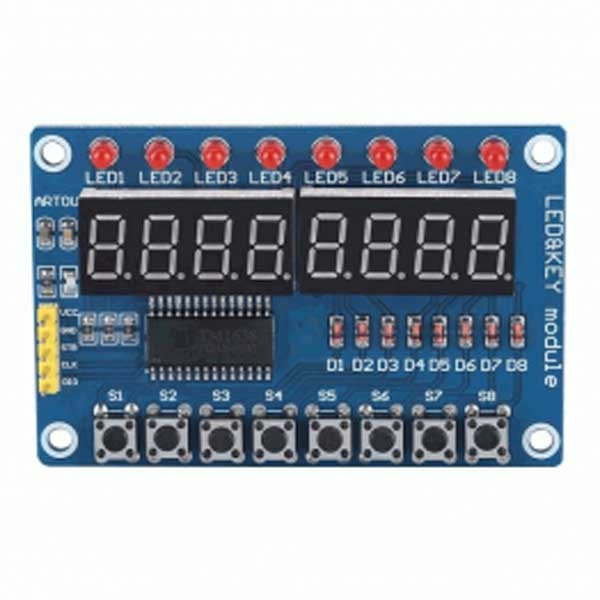

TM1638 8-Digit Tube LED Display Module
- 10 segments × 8 bits display
- Keypad scanning (8 × 3 bits)
- Brightness adjustment circuit (8-level adjustable duty ratio)
- Serial interfaces (CLK, STB, DIO)
- Oscillation mode: RC oscillation
- Built-in power-on reset circuit
- Package type: SOP28
And here is its interface/control pin function (again from the datasheet):
- DIO: Input serial data at rising edge of the clock, starting from lower bits. Output serial data at falling edge of the clock, starting from lower bits. During output, this is a PMOS open drain output
- CLK: Read serial data at rising edge and output data at falling edge
- STB: Initialize the serial interface at falling edge, then wait to receive instructions. The first byte after STB becomes low is considered as an instruction. When an instruction is being processed, other current processes are terminated. When STB is high, CLK is ignored.
Take note, when DIO outputs data, it’s an NMOS open drain output. In order to read the keypad, an external pull-up resistor (1K-10K) must be used. Furthermore, at the falling edge of the clock, DIO controls the operation of NMOS, at which point, the reading will become unstable until the rising edge of the clock.
Run a quick test:
An utterly simple way to take a test run of the TM1638 is to connect it with an Arduino board because the module is just a nifty piece of hardware but comes with zero documentation. If you want to learn how your TM1638 module works, you should spend countless hours searching for more information on its background electronics. Better, opt for proven Arduino Libraries as they’re most helpful for taking a (layman’s) quick test. Hopefully you can make something serious and useful later! This is the download link of one TM1638 Arduino Library by Ricardo Batista I quickly found in GitHub https://github.com/rjbatista/tm1638-library.
My first thought was to use an example sketch from the aforesaid library to test my quick setup. Later I searched for a useful piece of example code without any ‘beefy’ library and came across a pretty great demo code by MOOZZYK ARDUINO. Since I got the clever code working with my Arduino Uno. I’m sharing the same piece of code below (I still have lots to look at).
Now you have enough resources to breathe life into the display module. First you need to connect the module with your Arduino board. This is how I wired it:
Package Included:
- 1pc * TM1638 8-Digit Tube LED Display Module

